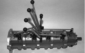
Valve Bodies – What is the Goal?
Over the past few decades valve bodies have become the single most complicated part of the transmission. The control has become very complex as we’ve gone from simple 4 speeds to electronically controlled 6, 7 and now even 10 speeds. They have also become one of the critical areas where wear causes other parts in the transmission to fail when operating pressures cannot be maintained. They are also the most difficult part to repair as this wear can be hard to see with the naked


Figure 1: 4L80E Valve Body | Figure 2: 6HP26 Valve Body
or untrained eye. Equipment such as the Hydra-Test VBT Deluxe gives
you the ability to see this wear hydraulically and find the specific circuit
issues as you can compare them against a new or known good valve body when
operated under the same conditions.
But
this does bring us back to what the overall goal is when it comes to valve
bodies? Are we trying to build a better valve body, one that sits us back into
the seat with each shift giving uncompromised performance? Are we trying to
restore to a new OEM function? Are we just trying to get it out of our shop and
down the road?

Figure 3: ZF 8HP Valve Body Under a Hydraulic
Test
Before the advent of the electronic valve
body, performance valve body kits were common. There were many performance kits
that would modify the shift characteristics of the valve body and give you a
firmer shift. I am sure more than one of us bought one of these in our younger
years for our “hot rod” and loved the feeling of performance on each shift.
Unfortunately, I’m also sure Mom thought otherwise, complaining when she rode
with us “What’s wrong with your car? I thought you said you fixed it? This
isn’t good for my neck!”
Modern valve bodies are really a part of a larger control system. Valve bodies are linked to TCUs and these TCUs have specific calibrations that have been developed for the engine/transmission combination in the vehicle as well as for the vehicle itself. Inputs from the engine and other controllers in the vehicle are taken into account as the TCU decides what gear to be in and when to upshift or downshift. The TCU’s uses complex feedback loops to determine if upshifts and downshifts happened correctly and if not they adapt to correct into the expected limits. When they cannot adapt any further, they signal a fault code and that is usually when we see it in your shop.
Given this, we can easily see how the
concept of a shift kit for a modern valve body would work against the TCU and
likely cause far more problems that it would fix. Today, changes to the
shifting logic are accomplished by modifying the calibration in the TCU. While
there are kits that do apply some form of modification, it tends to be more
along the lines of creating better lubrication or a more stable pressure rather
than changing the actual shift characteristics. With the valve body so
connected to the other parts of the vehicle we are not trying to build a better
or different valve body.
Just trying to get the vehicle out of our
shop and down the road is probably not what we are after either. If the
transmission barely makes it past the warranty period or worse yet fails before
the warranty period is up, the customer will not forget and shift issues, even
if they do not show up as fault codes will make for a very unhappy customer. We
all know the saying “A happy customer will tell his friends, and unhappy
customer will tell everyone!” Our goal
is to build a good quality unit that we can stand behind and really offer the
value that customers are seeking when they bring their vehicle to us.
That means that we should aim to restore
the valve body to new OEM function, right? Any moving part inside the valve
body will exhibit some wear over time, therefore the only way to restore
function to brand new, would be to replace the valve body with a brand-new
valve body. A more realistic goal on a rebuild is to find the areas of wear
that have significantly impacted the function of the valve body and restore
them as close as possible to OEM function. If solenoids are no longer able to
regulate pressure smoothly and in a controlled fashion, they should be
replaced. If springs are weak or broken and a valve is not controllable then the
spring needs to be replaced. If a bore for a valve has worn and is no longer
sealing properly around a valve, then the bore and valve needs to be addressed
which usually requires reaming and the use of an oversize valve.
As we perform work on a valve body, keep in
mind that the valve body is a delicate part of the transmission. Cleanliness is
of paramount importance, as well as taking care of each part. Accidentally
dropping valves from the valve body could bend them slightly and cause the to
stick once back inside the valve body. Solenoids are also delicate, and care
must be taken when handling them. Several years ago, I was visiting an OEM
working on a machine for their remanufacturing line. They told me from time to
time in their haste the forklift operators would “drop” a crate of new
solenoids as they moved them from the warehouse. If this happened, they would
not take the chance with them and the entire crate was taken to the dumpster.
Reaming out a valve bore is a process that must be done properly or you can cause more damage than good. If you take a new valve body and look down the bore, you see that it is smooth and machined with precision. When we ream a bore for an oversize valve, we need to get these same results. Think about the last time you were at a machine shop and saw parts in a CNC. What is critical for a machine shop when they are machining? Sharp cutting bits, the workpiece properly held in a fixture, the correct feed speeds, and plenty of lubrication/coolant while machining.

Figure 4. The reaming goal, a smooth bore on
a new valve body
If
you take a hand drill and a sharp drill bit and drill a one inch deep hole into
a piece of aluminum, it may seem like you can drill a smooth precise hole if
you are careful and delicate with it, but once you are done if you look at the
hole, you will see that the bore isn’t smooth and shiny. You can see the marks where
the drill bit cut as it went and wobbled as we tried to hold the drill steady.
Granted, using a ream in an existing hole is a lot less aggressive than a drill
bit, but this is where a good fixture, even feed speeds, and being flooded with
coolant makes all the difference. If we end up with a bore that looks like the
hole we tried to drill, you have poor sealing between the bore and the valve
and could have the same or worse issues that the valve body originally had.
I really want to emphasis how critical
flooding with lubrication/coolant is. I have watched reaming done by hand using
a spray bottle and a couple of squirts of fluid. When you flood the area you
are reaming it not only lubricates the ream to avoid sharp cut marks and
chatter, but also washes the material we are cutting away from the bore to keep
it from being drug around the ream in the bore as we continue the length of the
hole. Again, think back to the last time you were at a machine shop and the
kind of finish they can get on parts out of the CNC machines. We are aiming for
this same type of a process on the valve body.
I also want to emphasis that the use of a
fixture to help guide the ream. As steady as we all like to believe our hands
are, a fixture to guide the ream and hold the valve body steady is necessary
for accuracy when performing this operation. If you find yourself doing more
than a few of a particular valve body, it might be well worth it to invest in a
fixturing to be able to perform this on a milling machine. The valve body and
reaming bit can be held true and feeds and speeds can be tightly controlled.
This gives you the ability to get a high-quality ream every time.
The last step of the process is to check
your work. There are a few different ways to check and see if the reassembled
valve body is functioning properly before putting it back into the transmission
and the vehicle. The best and most
comprehensive way is to hydraulically test it in a valve body test machine

Figure 5: Hydra-Test VBT Deluxe
such
as the Hydra-Test VBT Deluxe where you can simulate the real in vehicle
operating conditions and be able to measure and graphically compare the valve
body against a known good master valve body. This allows you to check many of
the different circuits and compare against other units you have repaired using
pressure gauges or a graphical display. This method allows you to record and
analyze the pressures in the valve body and how they respond over time and to
varying of the control solenoid current. Another method involves vacuum testing of individual
circuits or valves on the valve body. There is plenty of information on this
procedure if you do a quick google search, so I will not detail the process
here. Lastly, you can just install it in the vehicle and take a test drive. If
you were able to address all of the valve body wear issues, you should be able
to clear all the codes and can run it through the learn cycle successfully.

Figure 6: Hydra-Test Graphical Pressure
Comparison
One
of the most challenging parts to this process is learning each different valve
body and what typically wears on each unit. While there are some common things
that seem to wear in every unit, each one has its own nuances which may differ
depending upon if the vehicle spends its life in and urban or rural
environment. As you work through this process, you also learn what areas
consistently need to be addressed. While this can be painstaking in the
beginning, the process does become easier with each valve body. Consistency in
your repair methods and test methods is key to the process and achieving
successful results that make both you, and your customers happy.


