


Transmission Solenoid Test Methods
The variety and shape of solenoids used in modern transmissions changes with each new model. On any rebuild, solenoids are a suspect part and should either be tested and verified for proper operation or replaced. Some shops opt to just replace all the solenoids on the valve body. On some models that makes sense as the replacement solenoids are fairly cost effective. For other models, the cost of either OEM or aftermarket replacement solenoids do make it worthwhile to test and only replace the ones that are worn or faulty.

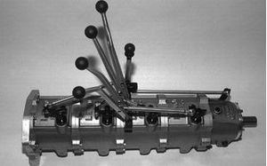
Figure 1: Hydra-Test HT Sol Solenoid Test Machine
When
you test a solenoid, a hydraulic solenoid testing machine with specific
adapters for each solenoid is by far the best and most accurate way to test. The
Hydra-Test HT Sol has become the industry standard for solenoid testing with a
range of adapters that can fit most any solenoid.
The
machine comes with full documentation and can guide you through the testing
process. For the purpose of this article, I am not going to go into detail on
the HT Sol. I want to focus on the basic solenoid and testing terminology such
as how you can identify solenoid types, and what kinds of a test methods you
would use to accurately test the different solenoids. A good understanding of
this will give you a good understanding on what you are trying to achieve when
you are testing.
Let us start with some characteristics and terminology used when talking about solenoids.
Solenoid Resistance:
One of the key measurements of a solenoid
is to use a multimeter to measure the resistance of the coil. This is a quick
and easy check where you can find if you have a short circuit, open circuit, or
the possibility of a partially shorted solenoid coil. An important thing to
remember is that when you measure the resistance, you are measuring the
resistance of the coil, which is a very, very long piece of wire. Unlike a true
resistor, where the resistance stays constant over a wide temperature range,
the resistance of a solenoid coil will measurably change over temperature (for
example between room temperature and 200F).
Normally Open or Normally Closed:
This refers to the hydraulic state of the solenoid when it is off with no electricity applied. A normally open solenoid would allow oil to flow from the inlet to the outlet. A normally closed solenoid would block oil between the input and output. Applying power to the solenoid will switch it to the opposite state. Sometimes these solenoids can be almost identical and will fit in the same hole on a valve body. You can imagine the shift issues that can be caused if this happens so be sure to double check.
Electrical Solenoid Activation:
This refers to how the solenoid is electrically driven when it is energized. The simplest method is to energize it with ignition voltage and allow it to draw full current. The next most common method is to use pulse width modulation (PWM). PWM is pulsing the solenoid on and off many times a second, and the amount of on time vs. the amount of off time is varied to change the amount of average current the solenoid will draw. There is one other method that called peak and hold that I will detail in another article. This method is used by Chrysler and it is similar to PWM but allows the ability to regulate current slightly differently on low resistance solenoids.
Generally, solenoids can be categorized into two types. The first is an on/off where the solenoid either allows full pressure at the outlet or blocks pressure to the outlet. The second is a pressure regulating solenoid where the output pressure from the solenoid is regulated to a desired valve by the varying the current draw of the solenoid.

Figure 2: PWM Definition
On/Off Solenoids:
- On/off solenoids are generally smaller in construction.
- On/off solenoids have higher resistance and if you measure the resistance it is usually greater than 10 ohms.
- Continuous current through these solenoids is around the 0.4-0.7 A and they are designed to handle that amount of current indefinitely.
- These solenoids were the primary used as shift and torque converter clutch solenoids in early applications. As transmissions and shift strategies have become more complex, they have been replaced by regulating solenoids.
- These solenoids cannot regulate pressure and will apply full pressure to the outlet.


Figure 3: ZF Shift Solenoid | Figure 4: Honda Shift Solenoid
Testing On/Off Solenoids:
Testing of on/off solenoids is
straightforward. Pressure should be applied to the inlet and if it is normally
closed you should not see pressure at the outlet. Once energized with ignition
voltage, you should see pressure at the outlet. For a normally open solenoid,
the opposite is true. Pressure applied at the inlet should be seen at the
outlet and when it is energized with ignition voltage there should be no
pressure at the outlet.
One of the most important aspects of
testing an on off solenoid is that there is no leakage through the solenoid
when it is in the closed condition. While the solenoid may appear off, wear or
cracks internally could allow a small amount of fluid to leak past. If you see
leakage, the solenoid should not be reused.
Regulating Solenoids:
- These are larger in constructing and incorporate and internal regulating valve.
- These have various names such Electronic Pressure Control (EPC), Linear Solenoids, or Trim Solenoids.
- These have a lower resistance and if you measure resistance, it is generally less than 10 ohms.
- Continuous current through these solenoids is varied and can range from 0 to just over 1 amp.
- These solenoids are the most common type used in transmissions today and allow for the smooth application of clutch to clutch shifting as well as the smooth control of the torque converter clutch.

Figure 5: Asian Warner Linear Solenoid | Figure 6: Allison Trim Solenoid | Figure 7: EPC Solenoid
Testing Regulating Solenoids:
Testing of regulating solenoids is a bit more complex. Pressure is applied to the inlet and outlet pressure should be observed as current is varied to the solenoid. Pressure should either increase or decrease with current depending upon if the solenoid is a normally open or a normally closed. These solenoids will have a maximum outlet pressure and applying excessive inlet pressure is not needed and could yield incorrect test results if the solenoid is over pressurized.
The most important aspect when testing a
regulating solenoid is that pressure changes smoothly as current is varied and
that the outlet pressure is always the same at a given current. Solenoids that
are worn will show a difference in outlet pressure at a given current. These
solenoids can also stick and have a dead spot where even though the current
changes, the outlet pressure remains the same. Lastly if the outlet pressure is
not steady and fluctuates rapidly at a given current, then this is an
indication that the solenoid may be having trouble regulating.
The best way to visually see how a regulating solenoid is performing is to sweep the current and graph this against pressure. A sweep from zero to max (1-1.3 amps) and back to zero should reveal a smooth graph where pressure changes as the current increases and decreases. One key item to note is that the pressure at a given current value is nearly the same as you increase current and then decrease current to come back to the same current valve. This difference is called hysteresis. There will be some difference of this pressure value (or hysteresis), but it should be minimal. As regulating solenoids wear the hysteresis increases noticeably.
One last item that is important on regulating solenoids is that certain ones have an adjustment screw that allows adjustment of the pressure vs. current relationship, i.e., you will measure more or less pressure for all current values as you adjust the screw in or out. This adjustment screw should not be set to an arbitrary setting, but rather set to match a known “calibrated” solenoid. The TCM in the vehicle has an expectation of what this pressure vs. current relationship should be and you can easily adjust this outside it expected range. When adjusted outside the expected range the solenoid technically functions properly, but the pressure vs. current is now outside of what the TCM expects and this can cause shifting problems and fault codes.
Pressure regulating solenoids that do not have smooth pressure vs. current curves, fluctuate output pressure at a steady current, have large hysteresis values as you sweep them, or cannot be adjusted to match a known good pressure vs. current relationship indicate excessive wear or a faulty solenoid and should not be reused.

Figure 8: Solenoid Pressure and Current
Graph from HT Sol