


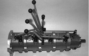


How are we testing solenoid?
Here are some common processes used regardless if you are a shop rebuilding a transmission on the bench or are a large reman with assembly lines for high volume production of units. In either case, there is a process of disassembly and determining what parts are good and can be reused, and which ones are bad and must be replaced. Many hard parts that can simply be inspected for wear, cracks, or other damage and determined very quickly if they are useable or not. Many soft parts are automatically replaced as they are not reusable. Between these two types of parts are the ones that require some level of testing to determine if they can be reused or if they need to be replaced. Solenoids are a prime example of such a part since a hydraulic test is required to determine if they are still functioning properly.
When we talk about testing, we not only
need to understand why we are testing it, but more importantly, the
how
do we test it
. The “why” is fairly straight forward, as we want to
determine if it is still functioning properly and that we can reuse it. The how to test it might not be as clear, and
there are multiple methods of how to test, and sometimes opinions on how to
test that are not always accurate. The basis of testing involves giving the
unit under test some type of a stimulus and measuring the response. Then we examine
the response and see if it is within an acceptable range or not to determine if
it passes or fails. The proper stimulus and what the acceptable range are is
things might get tricky.
So
how do we test a solenoid? The obvious answer might be to apply a hydraulic
pressure, apply an electrical current,
and observe the output pressure. In the case of
a variable pressure solenoid, different current points should produce different
output pressures and these pressure points should either increase or decrease
with current depending upon what type of solenoid it is, right? Well, that answer is partially correct.
I was on site with a customer once and we were testing a Ford 5R55E EPC solenoid. This solenoid is a good basic example of a pressure control solenoid and it is easy to see how as we increase current; the pressure should drop. The controller we had was able to vary the current to the solenoid in steps and you would set it to a value and then check on a pressure gauge the output pressure of the solenoid. I started with it off, then set it at 0.3 amps, then 0.7 amps, then 1.0 amps. The pressure decreased each time. I came back to 0.7, then 0.3, and finally back to 0, and the pressure increased with each test point. At each test point I stopped for about 20 seconds so we could check and read the pressure and discuss. The pressure readings matched what we expected. So, we concluded that this solenoid was fine, operating properly, and ready to be put onto the valve body, right? Wrong!
|
Increasing Current Steps |
Decreasing Current Steps |
||
|
Solenoid Current |
Output Pressure |
Solenoid Current |
Output Pressure |
|
0.0 |
90 PSI |
1.0 |
5 PSI |
|
0.3 |
80 PSI |
0.7 |
32 PSI |
|
0.7 |
30 PSI |
0.3 |
81 PSI |
|
1.0 |
5 PSI |
0.0 |
90 PSI |
This
same machine also had an option where we could increment these current steps
over time to “ramp” the current to the solenoid from 0 to a maximum and back to
zero. It would then graph the response on the computer screen so we could get a
clearer picture of what the solenoid response was. We set the max current to
1.0 amp and our total time for the ramp up and down to about 20 seconds and ran
the test. When we did this, we saw a vastly different picture. The solenoid
would drop pressure as expected as current increased, however as the current
decreased, the solenoid would stick for about 5 seconds at minimum pressure and
then snap to about half pressure as we continued decreasing current. This
repeated each time we cycled the solenoid as we ran it over and over again.
From the graph it was obvious we had a problem, which we could only see as we
continually increased or decreased the current, rather than just holding it
steady at certain current points. Today, this is easy to see on solenoids
machines such as the Hydra-Test HT Sol as this test and graphical method is the
basis for how their machine is designed to test. At the time I was working with
this customer, this method was more or less only done at large remanufacturers.

But as you can see, this gets to the very
root of the
how do we test it issue. We also need to understand
why one method indicated that everything was fine and the solenoid was working
properly, while the other clearly showed us a problem that would cause
drivability issues, would give fault codes, and possibly damage to the
transmission under certain conditions as our line pressure would be much lower
than expected in the unit.
Let us think about how this solenoid functions in the vehicle during normal operation. We want to test in the same way and try to mimic the real-world operating conditions as closely as possible. If we think about an EPC solenoid, especially one that is controlling overall line pressure, how does it operate as the vehicle as it goes down the road? Does it sit at a constant current or is the current constantly varying as the driver changes throttle position, if we are shifting gears, or if we apply the brakes? If you answered that it is constantly varying, you are correct. There may be times when it will be constant (say a long stretch of highway where you keeping a constant speed and throttle), but each time we change an input, it ramps the current up or down over time, just like when we ramped the current and observed it on the graph. If we only look at a few points where the current is constant, we completely miss the bigger picture and the solenoid momentarily sticking before it snaps into place due to wear, internal contamination, or damage.
There are two takeaways from this. The first
is that a tool (in this case a solenoid test machine with a variable current
and graphing capability) is only as good as the operator and how they are using
it. It is important to think about and understand
how you are testing.
The second takeaway relates to testing equipment. If you have a good handle on
how to test you can also verify that the equipment you are purchasing has the
features and the ability to test properly. Is the ability to ramp solenoid
current and see a resultant graph a standard feature like on the HT-Sol or not?
Proper testing yields good results and will save you both time and money, as
well as the frustration of chasing a bad part that tested “good” because of
incomplete testing.